| Hot Rod for 2000: Dual Celeron
by Leonard "Viking1" Hjalmarson |
||||
|
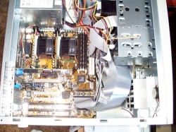
In the generic mini tower case supplied by a local vendor the entire mainboard is exposed. Power supply and drive bays don't obscure a single inch of the mainboard. Access to CPUs, main memory, ISA and PCI slots and even to SCSI and IDE connectors is all quick and painless. But there is more than that here. One only needs a quick glance at this board to see the pride in workmanship. There is a logic and symmetry to the layout that is immediately obvious. The board simply reeks of quality.
 Configurability is also the name of the game, and you can set up this system any way you like it. Bus speed and clock multiplier may be set via hardware or in the BIOS. There are FIVE plugs for cooling fans, including a smart fan outlet adjoining the AGP slot. The 649A supports the new Ultra II SCSI standard for maximum throughput to the CPUs. Since we will be enabling dual processing power totaling almost 1000 MHz, that becomes important. I confess to having very limited exposure to SCSI hardware to date, and so I was more than a little frustrated when I first assembled all this hardware only to have the system refuse to boot! I quickly sent emails to all the hardware geniuses associated with COMBATSIM.COM™ as well as to the tech support guys at Shuttle. In the meantime I began plugging and unplugging various devices and narrowed the problem down to a SCSI device. I then found that leaving the Toshiba CD ROM disconnected allowed the system to boot past the SCSI BIOS line. At that point I began playing with termination settings, on the mainboard, in the SCSI BIOS and on the CD ROM itself. No joy. Temporarily SOL I disconnected the offending device in favor of an IDE CD ROM, and from that device installed more software. |
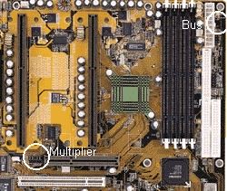
 Jumper Locations. Then early Monday morning I had an email from Mark Doran suggesting that I start with the simplest link: the SCSI cable itself. The idea had actually occurred to me earlier, but I didn't have one at hand and told myself this was a rare and unlikely occurrence. However, I obtained a new cable Monday morning and replaced the one that accompanied the Shuttle mainboard and VOILA! ... the system sprang to life with the SCSI CD in place. Jump for Joy The next task was to play with the bus clock and multiplier settings with a view to overclocking the 400As. I noted on first boot up that the system rang up an astounding 600MHz, which seemed to hint at great things. Thankfully I had the rear wheels tethered via logging cables to a ten ton concrete slab; the beast did not get away from me. Personally, I hate jumpers, and the soft BIOS settings would not allow me to go to a 6x or 100MHz bus. I placed another call to tech support on Saturday, hoping for a BIOS update or more clarity on Monday. Soft settings allowed me only 5x83, allowing boot up at 416 MHz. While waiting for tech support I decided to get dirty again. I put on the overalls and crawled under the beast for a look. The jumper locations are one of my few quibbles with the 649A. The image above shows the clock multiplier jumper position, essentially smack under the AGP video board. At top right you can see the bus speed jumpers, placed behind the power supply connector and smack against the extreme right edge of the mainboard. Once your drives are in place and cables attached access to this position remains possible, but is a strain. Go to Part V
|
|||
|
Copyright © 1997 - 2000 COMBATSIM.COM, INC. All Rights Reserved. Last Updated May 5th, 1999 |
||||
